[Japanese]
Usage of KUE-CHIP2 Simulator JAVA
Overview
All operations from entry of a program to its execution are identical with
the real KUE-CHIP2 educational CPU board.
However, following four points differ from it.
- Entry method of a program and data using Memory Editor.
- Editing method of a value of a register and a flag.
- Visualization for internal operation by block diagram.
- Displaying execution history of a user program on a Log Window.
This KUE-CHIP2 simulator consists mainly of two subsystems.
- Display subsystem
- This subsystem displays internal conditions such as registers and flags in
KUE-CHIP2 on some LEDs and seven-segment displays.
- Control subsystem
- This subsystem controls the operation of the KUE-CHIP2 simulator.
You can see the conditions of simulator on the display subsystem
at upper half of display area,
and operate it through the control subsystem at lower half of that.
You can also invoke some utilities, such as Memory Editor, from the control subsystem.
About Menu
Applet Edition displays a menu as a separated window at startup.
This is because applet cannot have a menu bar.
If the menu window appears at wrong size, please resize it manually into appropriate size.
Stand-alone Eition has a menu at the top of a window.
Display subsystem
Display subsystem has following LEDs and seven-segment displays.
|
Display Device
|
Function
|
| OP (LED) |
Light up when a program is running |
| P0~P4 (LED) |
Execution clock phase |
| CF,VF,NF,ZF (LED) |
Indicate conditions of Flags.
If the flag is set, the corresponding LED will light up. |
| INF, IN (LED) |
The input value by IN instruction in binary format |
| OUTF, OUT (LED) |
The output value by OUT instruction in binary format |
| PC (7-segment) |
Program Counter (PC) in hex format |
| IR (7-segment) |
Instruction Register (IR) in hex format |
| ACC (7-segment) |
ACC register in hex format |
| IX (7-segment) |
IX register in hex format |
| MAR (7-segment) |
Memory Address Register (MAR) in hex format |
| Address (7-segment) |
Accessing address in hex format |
Control subsystem
Control subsystem has following buttons.
| Control Button |
SS |
Run a program until HALT instruction.
If you push this button while a program is running,
the simulator will stop before fetching the next instruction.
|
| SI |
Step only one instruction of the program.
|
| SP |
Step only one clock phase of the program.
|
| RESET |
Reset KUE-CHIP2 simulator into initial state.
All registers and flags will be set to zero.
|
| CLOCK |
Clock speed can be set in five steps by pull-down menu.
|
| Tool Button |
MEMORY |
Toggles display of memory editor window.
|
| BLOCK |
Toggles display of block diagram window.
|
| LOG |
Toggles display of log window.
|
| Instruction |
Displays the current instruction in mnemonic form.
|
| Total Phase |
Displays total number of phases from beginning of the program.
|
| Total Instruction |
Displays total number of instructions from beginning of the program.
|
| State |
Displays current status of the simulator.
It is represented as following four status.
- RESET (Just at the reset)
- BREAK (Stop at a break point)
- RUNNING (Program is running)
- STOP (Program is not running)
|
Both Applet Edition and Stand-alone Edition
Use Memory Editor to enter a program.
When you press MEMORY button on Control subsystem,
Memory Editor will appear as a window which is separated from your browser.
You can input your program into arbitrary address in byte by byte using this window.
Program code must be in hex format.
First, click a value by mouse to reverse it.
You have to reverse only one byte.
After that, you may type new value in hex format with keyboard.
In this way, you will enter the program in byte by byte.
Only for Stand-alone Edition
You may import a program from a text file.
Specify the program file in a dialog box after selecting [File]-[Open..] menu.
Format of Program File
A text file which contains a program must be written in following format.
- Strings which begin with "#" are recognized as comment.
- Read into memory per byte (two hexadecimal digit).
- Ignore all characters except 0~9???A~F, a~f???(), [], and #.
Therefore, any other characters can be inserted at byte boundary.
Ex. (10) 11, 22, 33-44:55@44
This sample program will be placed in following order.
| Address | 010H | 011H | 012H | 013H | 014H | 015H |
|---|
| Data | 11H | 22H | 33H | 44H | 55H | 44H |
|---|
- One byte which is surrounding "(" and ")" represents
address for program area.
The values which followed the specified address are placed sequentially into the memory.
Ex. (00)6c 60
First, set 00 as address for program area.
Second, set 6CH into address 00, and set 60H into address 01.
- One byte which is surrounding "[" and "]" represents
address for data area.
You can entry data into memory as entry of program.
In Stand-alone Edition, you can import data from a text file.
You must specify a target address by "[]" in the file.
Execution of Program
Executing program is follow the same sequence as KUE-CHIP2 educational CPU board.
First, push RESET button to reset all internal conditions
of the simulator.
Next, use SS, SI and SP buttons to step the program.
Filling, Editing and Saving Memory
|
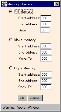
The dialog box on the right will appear when you select [Operation...] from [Memory] menu.
You can modify memory by following three operations from this dialog box.
Select one of three radio buttons.
- Fill Memory
- You can fill memory range (from Start address: to
End address:) with a value Data:.
- Move Memory
- You can move memory range (from Start address: to
End address:) to destination address Move to:.
After this operation, the source memory range will be filled with zero.
- Copy Memory
- You can copy memory range (from Start address: to
End address:) to destination address Copy to:.
|
|
|
In Stand-alone Edition, you can save all memory into a file by selecting [Save Memory...]
from [File] menu.
This file is read into memory by selecting [Open...] from [File] menu.
|
Editing Registers and Flags
- Editing Registers
- Click a seven-segment display on which you want to change value of register.
Type new value in hex format after the clicked display changes into reverse.
- Editing Flags
- Click a LED on which you want to change status of flag.
The status will toggle by clicking.
Setting a Breakpoint
You can set a breakpoint separately for each register (PC, IR, MAR, ACC, and IX).
A program will stop at the breakpoint when its condition is satisfied.
For example, if you set break condition to 03H for PC,
the program will stop when PC reaches 03H.
At the time, BREAK will be displayed in the State: column.
Break condition is set on a small seven-segment display beside a seven-segment
of each register.
The small seven-segment will be highlighted after you click it by the mouse.
Then you can enter a value in hex format from the keyboard.
If you want enable this break condition, select [Break point on] from [Control] menu.
Then the menu item will be changed into [Break point off].
Also, you can disable a breakpoint by selecting [Break point off]
even if you have already set a value as a breakpoint.
Click a value and type "-" (hyphen) from the keyboard to disable (reset) the value.
Logging of Execution History
First, click a LOG button on the control subsystem to open
a Log Window.
To begin logging, select [Start Log] from [Log] menu on the window.
All execution histories will be displayed in the window.
The menu item changes into [Stop Log] while the logging.
You can stop the logging by clicking [Stop Log].
You can clear all contents of the log window by selecting [Clear Log]
from [Log] menu.
In Stand-alone Edition, you can save the contents of the log window
by selecting [Save Log...] from [File] menu.
Back to the KUE-CHIP2 Simulator JAVA page